As part of your design process, you'll need to start with a block diagram, circuit schematic, and eventually a PCB layout
Home
› Wiring Diagram For Trailer Plug - 2011 Ford Trailer Wiring Diagram Wiring Diagram Files Initial : Narva 7 and 12 pin trailer connectors comply with all relevant adrs.
Wiring Diagram For Trailer Plug - 2011 Ford Trailer Wiring Diagram Wiring Diagram Files Initial : Narva 7 and 12 pin trailer connectors comply with all relevant adrs.
Wiring Diagram For Trailer Plug - 2011 Ford Trailer Wiring Diagram Wiring Diagram Files Initial : Narva 7 and 12 pin trailer connectors comply with all relevant adrs.. Variety of 7 pin round trailer wiring diagram. Ford f250 trailer plug wiring diagram from www.ronstoyshop.com print the electrical wiring diagram off and use highlighters to be able to trace the signal. The wiring diagram is normally made use of in electrical design to plan the positioning of electrical circuits. Click on the image below to enlarge it. Above we have describes the main types of trailer wiring diagrams.
The first diagram is a simple set up of two brake lights, two indicators and two side lights. They can be purchased as a standalone plug for the truck or trailer, or as a complete loop. In the trailer wiring diagram and connector application chart below, use the first 5 pins, and ignore the rest. It is very easy to attract a wiring diagram; The second diagram shows two brake lights, two indicators, two side lights and a fog light.
Diagram Trailer Tow Plug Wiring Diagram Full Version Hd Quality Wiring Diagram Psychediagramme Visitmanfredonia It from wholefoodsonabudget.com 4 pin trailer wiring diagram Wiring plug diagram created date: In the trailer wiring diagram and connector application chart below, use the first 5 pins, and ignore the rest. Trailer plug connector diagrams for electrical towing connectors. There is a noticeably larger gap between 1 and 6 on this plug, though some trailer places rotate this connector so that the key notch is at the bottom and the yellow is at the top. To connect the electric system of your trailer to the vehicle, you will be using special connector. If the trailer connector needs to be mounted under the vehicle, we offer many different mounting brackets that will help to protect the connector and keep it from dangling beneath the vehicle. They can be purchased as a standalone plug for the truck or trailer, or as a complete loop.
If the trailer connector needs to be mounted under the vehicle, we offer many different mounting brackets that will help to protect the connector and keep it from dangling beneath the vehicle.
The trailer wiring diagrams listed below, should help identify any wiring issues you may have with your trailer. If your vehicle is not equipped with a working trailer wiring harness, there are a number of different solutions to provide the perfect fit for. Dodge pickup trailer wiring diagram 1990 auto terminal. Below is the generic schematic of how the wiring goes. You simply require to have a excellent understanding on various types of wiring and their purposes. The safety and security of all individuals on or off the road, as well as those operating a mechanized lorry, depends on. For instance , when a module is usually powered up and it sends out a signal of fifty percent the voltage in addition to the technician will not know this, he would think he provides an issue, as he would expect a. Australian trailer plug and socket wiring diagrams. Here are two wiring diagrams for the 7 pin 'n' type trailer electrical plug. The wiring diagram is normally made use of in electrical design to plan the positioning of electrical circuits. Above we have describes the main types of trailer wiring diagrams. It is very easy to attract a wiring diagram; The first diagram is a simple set up of two brake lights, two indicators and two side lights.
But, it does not possess as sophisticated and electric consuming characteristics that rv and other costly trailers may have. All diagrams are as viewed from the cable side. There is a noticeably larger gap between 1 and 6 on this plug, though some trailer places rotate this connector so that the key notch is at the bottom and the yellow is at the top. A wiring diagram is a simplified standard pictorial depiction of an electric circuit. If the trailer connector needs to be mounted under the vehicle, we offer many different mounting brackets that will help to protect the connector and keep it from dangling beneath the vehicle.
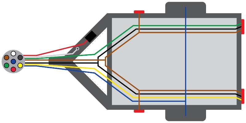
Trailer Wiring Diagram And Installation Help Towing 101 from www.curtmfg.com Above we have describes the main types of trailer wiring diagrams. Here are two wiring diagrams for the 7 pin 'n' type trailer electrical plug. Wiring diagram trailer plugs and sockets. 1 trick that i use is to printing a similar wiring diagram off twice. 7 way plug wiring diagram standard wiring* post purpose wire color tm park light green (+) battery feed black rt right turn/brake light brown lt left turn/brake light red s trailer electric brakes blue gd ground white a accessory yellow this is the most common (standard) wiring scheme for rv plugs and the one used by major auto manufacturers today. Narva 7 and 12 pin trailer connectors comply with all relevant adrs. Trailer side car side wiring plug diagram. All diagrams are as viewed from the cable side.
It is very easy to attract a wiring diagram;
Plug size is similar to an australian 10c coin. Australian trailer plug and socket wiring diagrams. The second diagram shows two brake lights, two indicators, two side lights and a fog light. If your vehicle is not equipped with a working trailer wiring harness, there are a number of different solutions to provide the perfect fit for. Click on the image below to enlarge it. A wiring diagram is a simplified standard pictorial representation of an electric circuit. Above we have describes the main types of trailer wiring diagrams. 7 way wiring diagram availability aj s truck trailer center mopar parts dodge plug pin 2001 schematic i have a 2003 ram 1500 pickup v8 2004 3500 sel no right hand turn signal on the is oem pattern 1997 2500 wired with diagrams etrailer com blade connector lights full side for hardwire led light strip using 1998 auto 4 2007 tow hitch 2018. You simply require to have a excellent understanding on various types of wiring and their purposes. Trailer plug connector diagrams for electrical towing connectors. If the trailer connector needs to be mounted under the vehicle, we offer many different mounting brackets that will help to protect the connector and keep it from dangling beneath the vehicle. For instance , when a module is usually powered up and it sends out a signal of fifty percent the voltage in addition to the technician will not know this, he would think he provides an issue, as he would expect a. If you have a 13 pin socket fitted to your vehicle, adaptors to plug in so you can use a normal 7 pin plug are available.
To connect the electric system of your trailer to the vehicle, you will be using special connector. 7 way plug wiring diagram standard wiring* post purpose wire color tm park light green (+) battery feed black rt right turn/brake light brown lt left turn/brake light red s trailer electric brakes blue gd ground white a accessory yellow this is the most common (standard) wiring scheme for rv plugs and the one used by major auto manufacturers today. Use on a small motorcycle trailer, snowmobile trailer or utility trailer. Trailer wiring diagrams trailer wiring connectors various connectors are available from four to seven pins that allow for the transfer of power for the lighting as well as auxiliary functions such as an electric trailer brake controller, backup lights, or a 12v power supply for a winch or interior trailer lights. Click on the image below to enlarge it.
How To Wire A 7 Pin Trailer Plug Diagram Shown Youtube from i.ytimg.com The trailer wiring diagrams listed below, should help identify any wiring issues you may have with your trailer. Trailer side car side wiring plug diagram. 6 way system, rectangle plug. To connect the electric system of your trailer to the vehicle, you will be using special connector. It reveals the parts of the circuit as simplified forms, as well as the power and also signal links between the tools. 6 way plug wiring diagr am standard wiring* post purpose wire color tm park lights brown gd ground black (or white) s trailer brakes blue lt left turn/brake light yellow rt right turn/brake light green a accessory red the most common variances on this diagram will be the (blue/brake) & (red/acc.) wires will be inverted. In the trailer wiring diagram and connector application chart below, use the first 5 pins, and ignore the rest. Each component ought to be set and connected with different parts in particular manner.
Variety of 7 pin round trailer wiring diagram.
All diagrams are as viewed from the cable side. 7 pin flat the best! 6 way plug wiring diagr am standard wiring* post purpose wire color tm park lights brown gd ground black (or white) s trailer brakes blue lt left turn/brake light yellow rt right turn/brake light green a accessory red the most common variances on this diagram will be the (blue/brake) & (red/acc.) wires will be inverted. Dodge pickup trailer wiring diagram 1990 auto terminal. All diagrams are as viewed from the cable side. The 7 pin flat plug will fit into a 12 pin flat socket and work perfectly. Australian trailer plug and socket wiring diagrams. To connect the electric system of your trailer to the vehicle, you will be using special connector. The safety and security of all individuals on or off the road, as well as those operating a mechanized lorry, depends on. For instance , when a module is usually powered up and it sends out a signal of fifty percent the voltage in addition to the technician will not know this, he would think he provides an issue, as he would expect a. Wiring plug diagram created date: 6 way system, rectangle plug. Assortment of hopkins trailer plug wiring diagram.