As part of your design process, you'll need to start with a block diagram, circuit schematic, and eventually a PCB layout
Home
› Wiring Diagram Plc Ladder Diagram / Plc Ladder Diagrams For Electrical Engineers / I'm using the siemens tia portal as the plc programming software.
Wiring Diagram Plc Ladder Diagram / Plc Ladder Diagrams For Electrical Engineers / I'm using the siemens tia portal as the plc programming software.
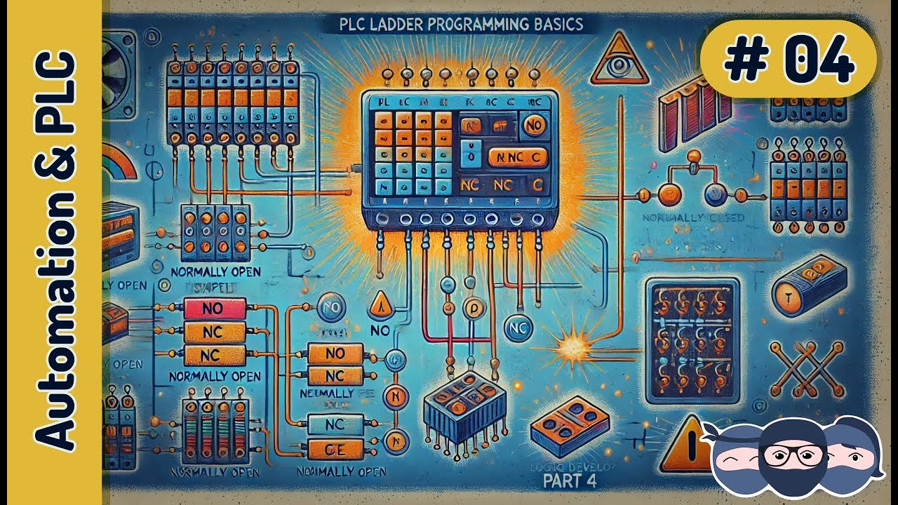
Wiring Diagram Plc Ladder Diagram / Plc Ladder Diagrams For Electrical Engineers / I'm using the siemens tia portal as the plc programming software.. We can redraw this diagram in a different way, using two vertical lines to represent the input power rails and stringing the. Below is an input card and ladder logic diagram that shows how to connect an ac input card. It has supply rails, relay coils, relay contacts, counters, timers, pid loop controllers and much. A simple explanation of plc ladder logic (ladder diagram). In the ladder diagram, the programming language that used to create the program to control the plc system is known as 'ladder diagram language' or 'ladder logic language'.
It has signified by the graphical representation, just like electrical wiring for logic control. A wiring diagram is an electrical print that shows connections of all components in a piece of equipment.a schematic diagram is a type of drawing that illustrates the electrical connections and functions of specific circuit arrangements with graphic symbols.a ladder diagram is a diagram that. When a controls cabinet is designed and constructed ladder diagrams are used to document the wiring. Ladder logic works in a similar way to relay logic, but without all the laborious wiring. Related posts of plc wiring diagram 133 best plc programming images in 2016 plc programming ladder.
Plc Ladder Programming 1 Learn Under 5 Min No Nc Contacts And Gate Logic Youtube from i.ytimg.com Plc ladder (running in simulation mode). One reason may be that i have used nc of s5 in network 2 and s5 (no) is directly connected to s3 in network 4. Motor control circuits ladder logic electronics textbook. (at the end of this article, i will. In the ladder diagram, the programming language that used to create the program to control the plc system is known as 'ladder diagram language' or 'ladder logic language'. This chapter introduces basic and advanced concepts of ladder logic, which is the most. The examples in this chapter use two simple instructions to help you learn how to write ladder diagram logic. Picture above represents a example of a ladder diagram where relay is activated in plc controller when signal appears at input line 0.
Plc ladder (running in simulation mode).
Plc ladder (running in simulation mode). Plc programming example sorting station shift register. Vertical line pairs are called conditions. Learn the programmable logic controllers starting with a simple example to the complex level logic.plc courses. Ladder diagram program get rid of wiring diagram problem. Ladder diagrams help you to formulate the logic expressions in graphical form that are required to program a plc. Share on facebook share on twitter. In this article we will discuss about plc circuit diagram of input and output module of plc. Basics of plc ladder programming. Plc ladder circuit examples, plc logo wiring, plc relay circuit, plc wiring connection, siemens plc wiring tutorial. Ladder diagram consists of one vertical line found on the left hand side, and lines which branch off to the right. Values may be inverted when using a plc with source type outputs. The diagram shows the circuit for switching on or off an electric motor.
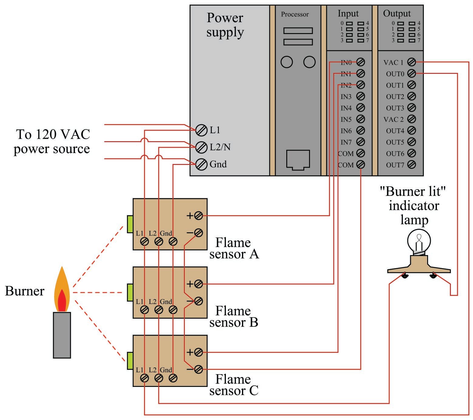
When wiring up the inputs and outputs to the plc, the relevant ones must be connected to the input and output terminals with these addresses. Ladder diagrams help you to formulate the logic expressions in graphical form that are required to program a plc. Each conductor has its own unique wire number for the control system that its used in. In short, it is to make sure that the system stops when a wire to the button breaks. Basics of plc ladder programming.
Ladder Diagram Ld Programming Basics Of Programmable Logic Controllers Plcs Automation Textbook from control.com Basics of plc ladder programming. (at the end of this article, i will. Vertical line pairs are called conditions. Ladder logic in programmable logic controllers plcs. Plc ladder circuit examples, plc logo wiring, plc relay circuit, plc wiring connection, siemens plc wiring tutorial. Share on facebook share on twitter. A wiring diagram is an electrical print that shows connections of all components in a piece of equipment.a schematic diagram is a type of drawing that illustrates the electrical connections and functions of specific circuit arrangements with graphic symbols.a ladder diagram is a diagram that. Values may be inverted when using a plc with source type outputs.
Fix this by inverting the actuators in the driver window for the board in use.
When a controls cabinet is designed and constructed ladder diagrams are used to document the wiring. Values may be inverted when using a plc with source type outputs. (at the end of this article, i will. A program in ladder diagram notation is a circuit diagram that emulates circuits of relay logic hardware. Plc ladder (running in simulation mode). They are called ladder diagrams these wire numbers make assembly and maintenance very easy. It has supply rails, relay coils, relay contacts, counters, timers, pid loop controllers and much. A basic wiring diagram is shown in. Ladder logic in programmable logic controllers plcs. The examples in this chapter use two simple instructions to help you learn how to write ladder diagram logic. Motor control circuits ladder logic electronics textbook. Basics of plc ladder programming. When wiring up the inputs and outputs to the plc, the relevant ones must be connected to the input and output terminals with these addresses.
We can redraw this diagram in a different way, using two vertical lines to represent the input power rails and stringing the. Picture above represents a example of a ladder diagram where relay is activated in plc controller when signal appears at input line 00. Ladder logic works in a similar way to relay logic, but without all the laborious wiring. In drawing ladder diagrams the names of the associated variable or addresses of each element are appended to its symbol. Electrical ladder diagram examples get rid of wiring.
Wiring Diagram Plc Omron from i0.wp.com The rules that you learn for these instructions apply to all other instructions. (at the end of this article, i will. This chapter introduces basic and advanced concepts of ladder logic, which is the most. A basic wiring diagram is shown in. Motor control circuits ladder logic electronics textbook. It has supply rails, relay coils, relay contacts, counters, timers, pid loop controllers and much. Learn the programmable logic controllers starting with a simple example to the complex level logic.plc courses. In ladder network 3 and 4, k3 is constantly on though no input is on (you can see plc config in right side).
Fix this by inverting the actuators in the driver window for the board in use.
Fix this by inverting the actuators in the driver window for the board in use. Outputs from plcs are often relays, but they can also be solid state electronics such as transistors for dc outputs or triacs for ac outputs. But since ld is top to down. A simple explanation of plc ladder logic (ladder diagram). Plc ladder circuit examples, plc logo wiring, plc relay circuit, plc wiring connection, siemens plc wiring tutorial. Values may be inverted when using a plc with source type outputs. A program in ladder diagram notation is a circuit diagram that emulates circuits of relay logic hardware. When a controls cabinet is designed and constructed ladder diagrams are used to document the wiring. Ladder diagrams help you to formulate the logic expressions in graphical form that are required to program a plc. Basics of plc ladder programming. Ladder diagram consists of one vertical line found on the left hand side, and lines which branch off to the right. (at the end of this article, i will. It has signified by the graphical representation, just like electrical wiring for logic control.