As part of your design process, you'll need to start with a block diagram, circuit schematic, and eventually a PCB layout
Home
› 3 Way Outlet Wiring Diagram : Swap Out Those Old Crappy 3 Way Light Switches For Good Cnet : Www.doityourself.com read hunter ceiling fan capacitor wiring diagram database before reading a schematic, get common and understand each of the symbols.
3 Way Outlet Wiring Diagram : Swap Out Those Old Crappy 3 Way Light Switches For Good Cnet : Www.doityourself.com read hunter ceiling fan capacitor wiring diagram database before reading a schematic, get common and understand each of the symbols.
3 Way Outlet Wiring Diagram : Swap Out Those Old Crappy 3 Way Light Switches For Good Cnet : Www.doityourself.com read hunter ceiling fan capacitor wiring diagram database before reading a schematic, get common and understand each of the symbols.. Search for wiring diagrams 3 way switch to 2 receptacles here and subscribe to this site wiring diagrams 3 way switch to 2 receptacles read more! Wiring 2 half hot receptacles 3 way switched outlet diagram switch diagrams do it is split controlled by switches plug full light recepticle electrical 101 with wire on 4 for wall how to a receptacle tracing circuits jlc online an kitchen 20a fusebox and page combo device multiple schematic hd png dc prug installation circuit style gang 5 lights. This wiring is commonly used in a 20 amp kitchen circuit where two appliance feeds are needed, such as for a refrigerator and a microwave in the same location. These switches have two traveler wires and a single common wire. In my case i'm doing it so that i can have more power available on the.
1 trick that we 2 to print the same wiring picture off twice. The 3 prong dryer wiring diagram here shows the proper connections for both ends of the circuit. Wiring diagram 3 way switch split receptacle source: This wiring is commonly used in a 20 amp kitchen circuit where two appliance feeds are needed, such as for a refrigerator and a microwave in the same location. Sometimes it is handy to have an outlet controlled by a switch.
3 Way Switch Variations from matthews.sites.wfu.edu The 3 prong dryer wiring diagram here shows the proper connections for both ends of the circuit. 3 way switch diagrams and connections ad#blockelectrical question: Www.doityourself.com read hunter ceiling fan capacitor wiring diagram database before reading a schematic, get common and understand each of the symbols. Find your wiring diagrams 3 way switch to 2 receptacles here for wiring diagrams 3 way switch to 2 receptacles and you can print out. Right now, each switch is functioning like a single pole, turning on/off the string of outlets rather than controlling the outlets as intended. The black and red wires between sw1 and sw2 are connected to the traveler terminals. It shows the way the electrical wires are interconnected and may also show where fixtures and components may be connected to the system. 3 way light switch to outlet wiring diagram from i.pinimg.com print the electrical wiring diagram off plus use highlighters to trace the signal.
I'm wiring the new workshop and want to use 3 way switches to control four outlets running across the ceiling for plug in lights.
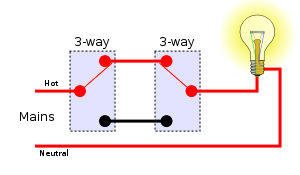
The neutral wire from the circuit is shared by both sets. For wiring in series, the terminal screws are the means for passing voltage from one receptacle to another. Ed, a handyman from hollis, new hampshire. As we power this circuit, electricity will flow through the hot wire over to the second switch. This wiring is commonly used in a 20 amp kitchen circuit where two appliance feeds are needed, such as for a refrigerator and a microwave in the same location. When you use your finger or perhaps the actual circuit along with your eyes, it is easy to mistrace the circuit. See more ideas about 3 way switch wiring, home electrical wiring, diy electrical. These switches have two traveler wires and a single common wire. The single pole switch has a neutral conductor for future electronic controls such as a timer or a wifi switch. The black and red wires between sw1 and sw2 are connected to the traveler terminals. Step by step instructions on how to wire a switched outlet. Right now, each switch is functioning like a single pole, turning on/off the string of outlets rather than controlling the outlets as intended. It shows the way the electrical wires are interconnected and may also show where fixtures and components may be connected to the system.
The neutral wire from the circuit is shared by both sets. Right now, each switch is functioning like a single pole, turning on/off the string of outlets rather than controlling the outlets as intended. See more about electrical wiring for new hampshire. These switches have two traveler wires and a single common wire. Wiring diagram of a switched electrical receptacle outlet and an unswitched electrical receptacle outlet with the power entering the switched outlet electrical box from the circuit breaker panel.
Multiway Switching Wikipedia from upload.wikimedia.org Outlet wiring for a table lamp or a floor light fixture. This wiring is commonly used in a 20 amp kitchen circuit where two appliance feeds are needed, such as for a refrigerator and a microwave in the same location. When you use your finger or perhaps the actual circuit along with your eyes, it is easy to mistrace the circuit. These electrical wiring diagrams show typical connections. See more about electrical wiring for new hampshire. For wiring in series, the terminal screws are the means for passing voltage from one receptacle to another. A circuit power supply source wire cable that is routed to outlet. 1 trick that we 2 to print the same wiring picture off twice.
3 way light switch to outlet wiring diagram from i.pinimg.com print the electrical wiring diagram off plus use highlighters to trace the signal.
In my case i'm doing it so that i can have more power available on the. Any break or malfunction in one outlet will cause all the other outlets to fail. See more ideas about 3 way switch wiring, home electrical wiring, diy electrical. Multiple outlet in serie wiring diagram : Find your wiring diagrams 3 way switch to 2 receptacles here for wiring diagrams 3 way switch to 2 receptacles and you can print out. As it goes through the red traveler, it will stop at switch number one. The neutral wire from the circuit is shared by both sets. With easy to follow diagrams and instructions, you can have that convenience in no time. To wire multiple outlets, follow the circuit diagrams posted in this article. 3 way light switch to outlet wiring diagram from i.pinimg.com print the electrical wiring diagram off plus use highlighters to trace the signal. Wiring diagram 3 way switch split receptacle. Www.doityourself.com read hunter ceiling fan capacitor wiring diagram database before reading a schematic, get common and understand each of the symbols. This electrical question came from:
Wiring 2 half hot receptacles 3 way switched outlet diagram switch diagrams do it is split controlled by switches plug full light recepticle electrical 101 with wire on 4 for wall how to a receptacle tracing circuits jlc online an kitchen 20a fusebox and page combo device multiple schematic hd png dc prug installation circuit style gang 5 lights. Outlet wiring for a table lamp or a floor light fixture. Right now, each switch is functioning like a single pole, turning on/off the string of outlets rather than controlling the outlets as intended. These electrical wiring diagrams show typical connections. One side of the gfci connected to the ground (neutral wire as shown white in the diagram) and another side to the high potential (hot wire shown as black in the diagram) shows as in black color.
How Do You Wire Multiple Outlets Between Three Way Switches Home Improvement Stack Exchange from i.stack.imgur.com Need help wiring a 3 way switch? Multiple outlet in serie wiring diagram : This wiring is commonly used in a 20 amp kitchen circuit where two appliance feeds are needed, such as for a refrigerator and a microwave in the same location. Www.doityourself.com read hunter ceiling fan capacitor wiring diagram database before reading a schematic, get common and understand each of the symbols. In my case i'm doing it so that i can have more power available on the. Find your wiring diagrams 3 way switch to 2 receptacles here for wiring diagrams 3 way switch to 2 receptacles and you can print out. Wiring diagram 3 way switch with light at the end in this diagram, the electrical source is at the first switch and the light is located at the end of the circuit. Wiring diagram 3 way switch split receptacle.
This size breaker requires a minimum of a #10 gauge wire so this wire used would be a 10/2 with ground.
The single pole switch has a neutral conductor for future electronic controls such as a timer or a wifi switch. For wiring in series, the terminal screws are the means for passing voltage from one receptacle to another. These switches have two traveler wires and a single common wire. Wiring diagram of a switched electrical receptacle outlet and an unswitched electrical receptacle outlet with the power entering the switched outlet electrical box from the circuit breaker panel. Wiring diagram 3 way switch with light at the end in this diagram, the electrical source is at the first switch and the light is located at the end of the circuit. One side of the gfci connected to the ground (neutral wire as shown white in the diagram) and another side to the high potential (hot wire shown as black in the diagram) shows as in black color. This electrical question came from: 3 way light switch to outlet wiring diagram from i.pinimg.com print the electrical wiring diagram off plus use highlighters to trace the signal. Outlet wiring for a table lamp or a floor light fixture. It shows the way the electrical wires are interconnected and may also show where fixtures and components may be connected to the system. This wiring is commonly used in a 20 amp kitchen circuit where two appliance feeds are needed, such as for a refrigerator and a microwave in the same location. Wiring diagram 3 way switch split receptacle source: The neutral wire from the circuit is shared by both sets.